
Building the GBS

 bygging av betongdelen til plattformen, juni 1990, engelsk
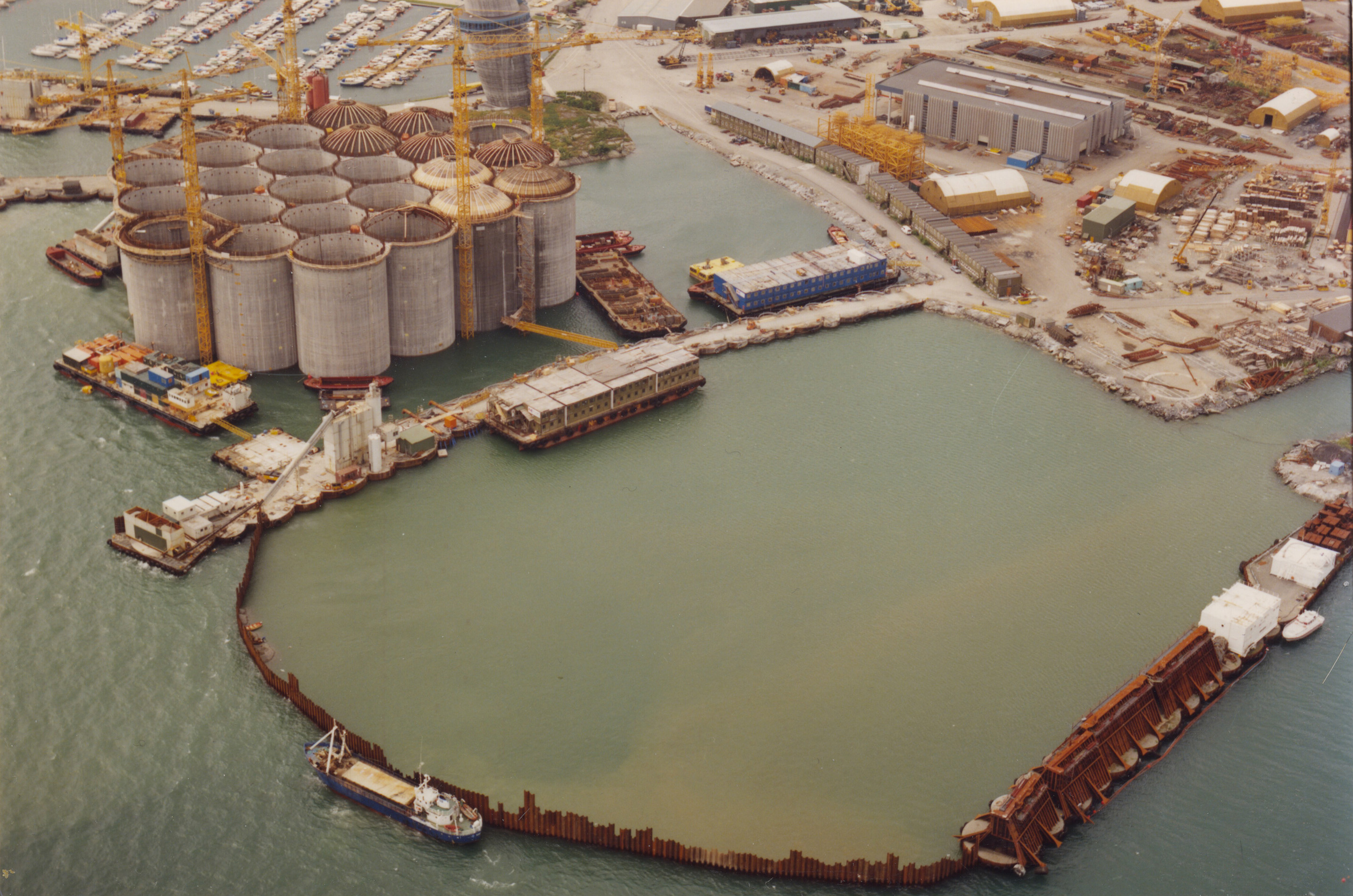
The sheet pile retaining wall for a dry dock at Jåttåvågen in Stavanger was established in June 1990. At the same time, plans were laid to tow the base section for the Gullfaks C GBS from the adjacent dry dock into the Gands Fjord immediately outside. The Sleipner A GBS lay already in the fjord.
During the summer, the dry dock was emptied of water and work could begin in August on the lowest part of the storage cells and central support shaft for the Draugen structure.
The first job was to cast the nine-metre-high skirts which would ensure that the platform would dig into the seabed and withstand all kinds of weather out on the field.
 bygging av betongdelen til plattformen, sept. 1990
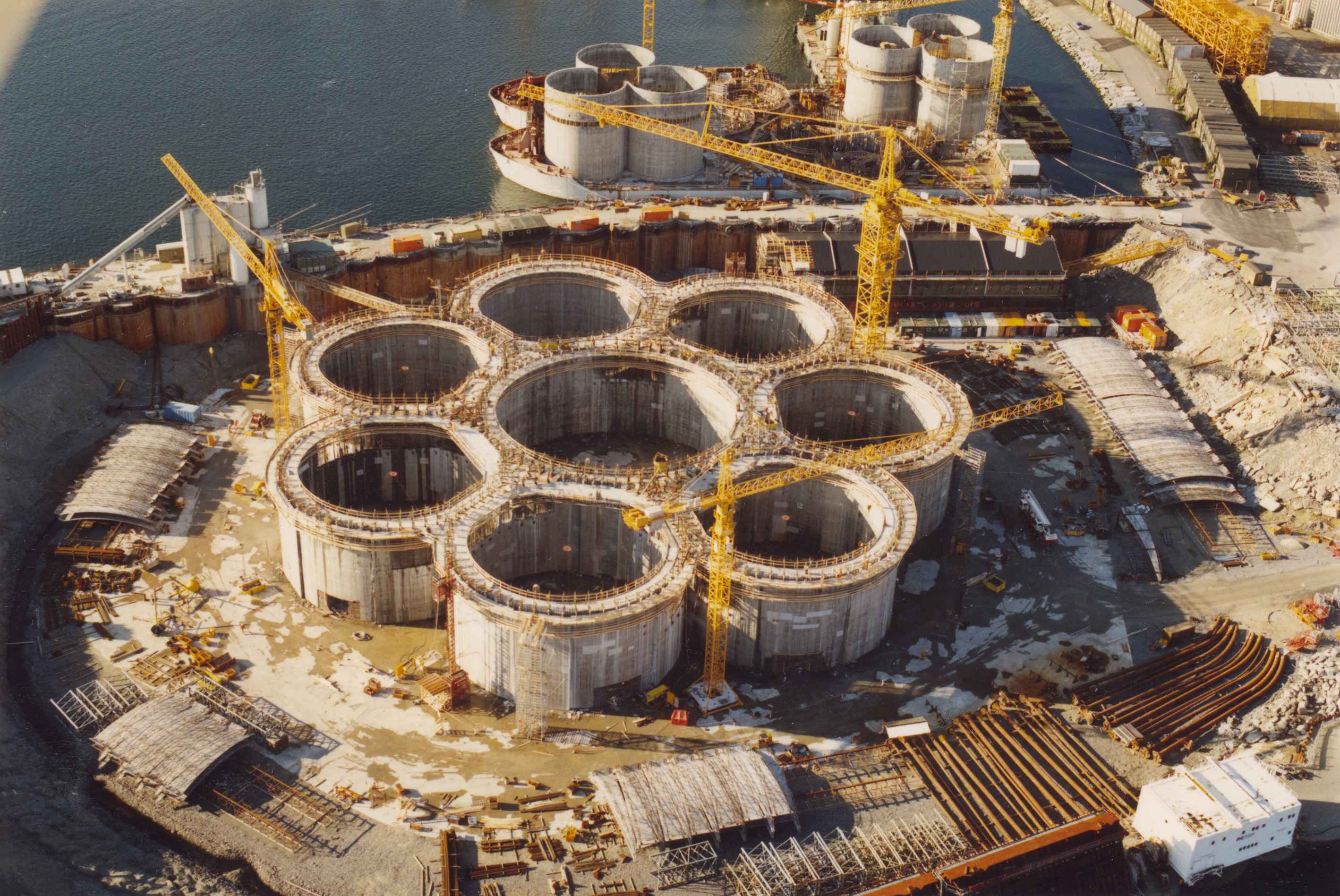
At the same time, the tethering blocks for the Snorre A concrete tension-leg platform were under construction on two barges moored alongside the dry dock.
Building four very different offshore structures simultaneously meant this was an extremely busy time for Norwegian Contractors (NC).
 bygging av betongdelen til plattformen, feb 1991, engelsk,
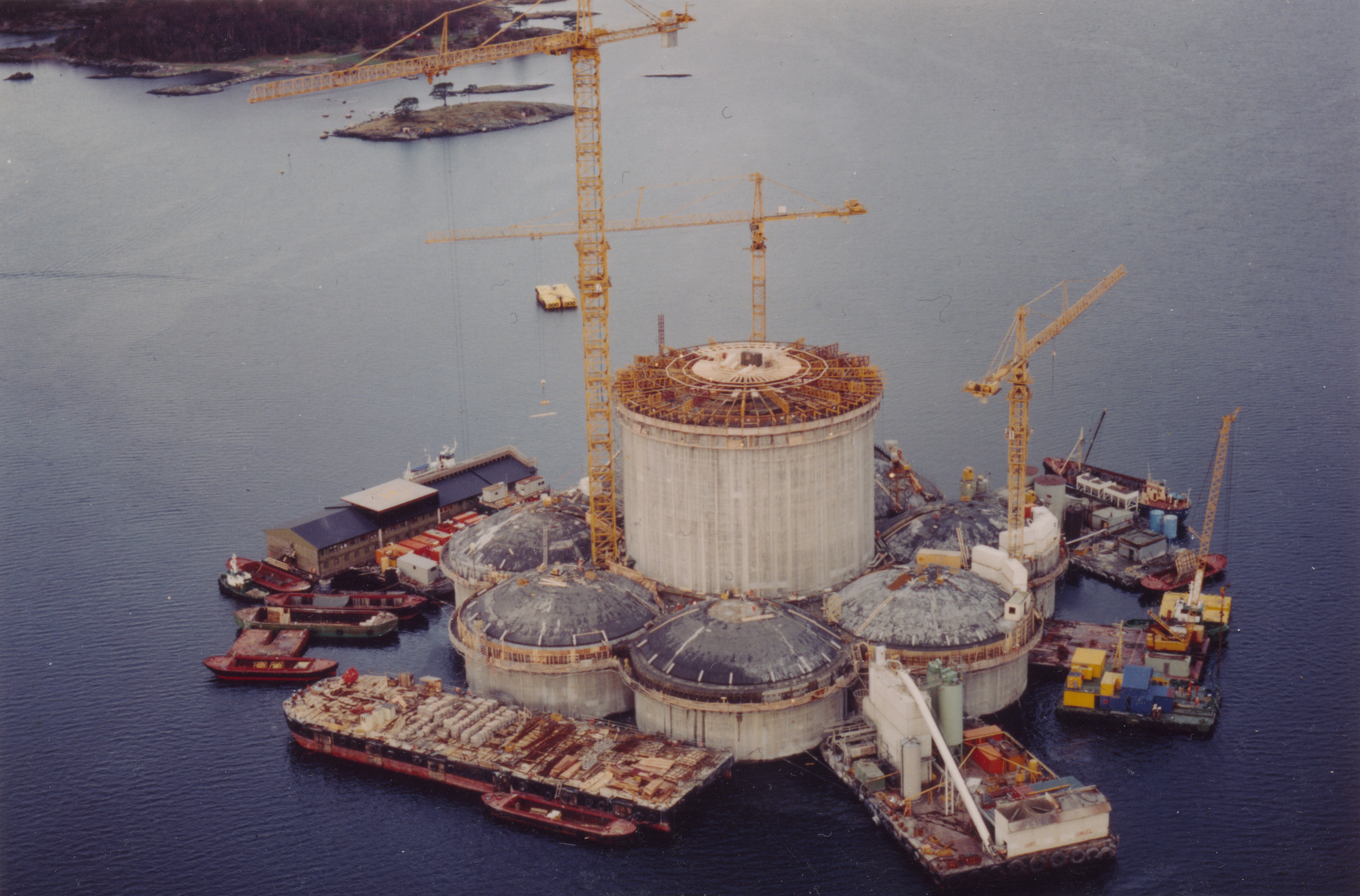
When the skirts had been completed in October, work could begin to construct the formwork for the actual storage cells. Before that got properly under way, however, the first mechanical outfitting for the support shaft was positioned in February 1991.
The bottom section of the GBS comprises seven oil storage cells clustered around a central cell, which forms the lowest part of the shaft.
Pipes conducting oil to and from storage run through the cell walls and into the central cell, where they terminate in a manifold measuring 80 centimetres in diameter.
This is shaped like a doughnut with a diameter of about 30 metres. All the pipes are manufactured in glassfibre-reinforced plastic (GRP) surrounded by reinforced concrete.
A conductor measuring 65 centimetres in diameter rises from the manifold to carry oil up to the topsides for treatment/processing and onward transport to a loading buoy.
During pressure-testing of this piping system, the cast-in manifold was found to have a leak. The chosen repair method involved sending people through the narrow pipe from about four metres above the manifold.
They had with them what was needed to seal the leak with epoxy.[REMOVE]Fotnote: Epoxy, or artificial resin, is a liquid plastic substance which fuses with the substratum to function as a glue. Simply getting a man down such a narrow tube by rope ladder was considered almost impossible, but these lads did it. And reaching the leak point with tools and materials in a pipe 80 centimetres in diameter as well as getting safely back out was also an achievement, of course.
They had a video camera with them to document the repair. In one of the shots, with the men bent over in the world’s narrowest workspace, one can be seen and heard to say with a grin: “This is a pipe show”.
One of the technological advances on Draugen was that almost all the pipe systems were in GRP. Although a positive development, this also presented NC with some surprises.
The company was unused to this material, admits NC project director Eivind Wolff. “While steel piping could be almost guaranteed not to leak, GRP presented a risk for leakage at the joints which we couldn’t ignore.
“And, given the substantial pressure on the cast-in tubing, we ran the risk that the concrete would simply collapse. A big increase in reinforcement was needed to document that the walls were strong enough.”[REMOVE]Fotnote: Interview with Wolff on 20 October 2016.
 bygging av betongdelen til plattformen, juni 1991, engelsk
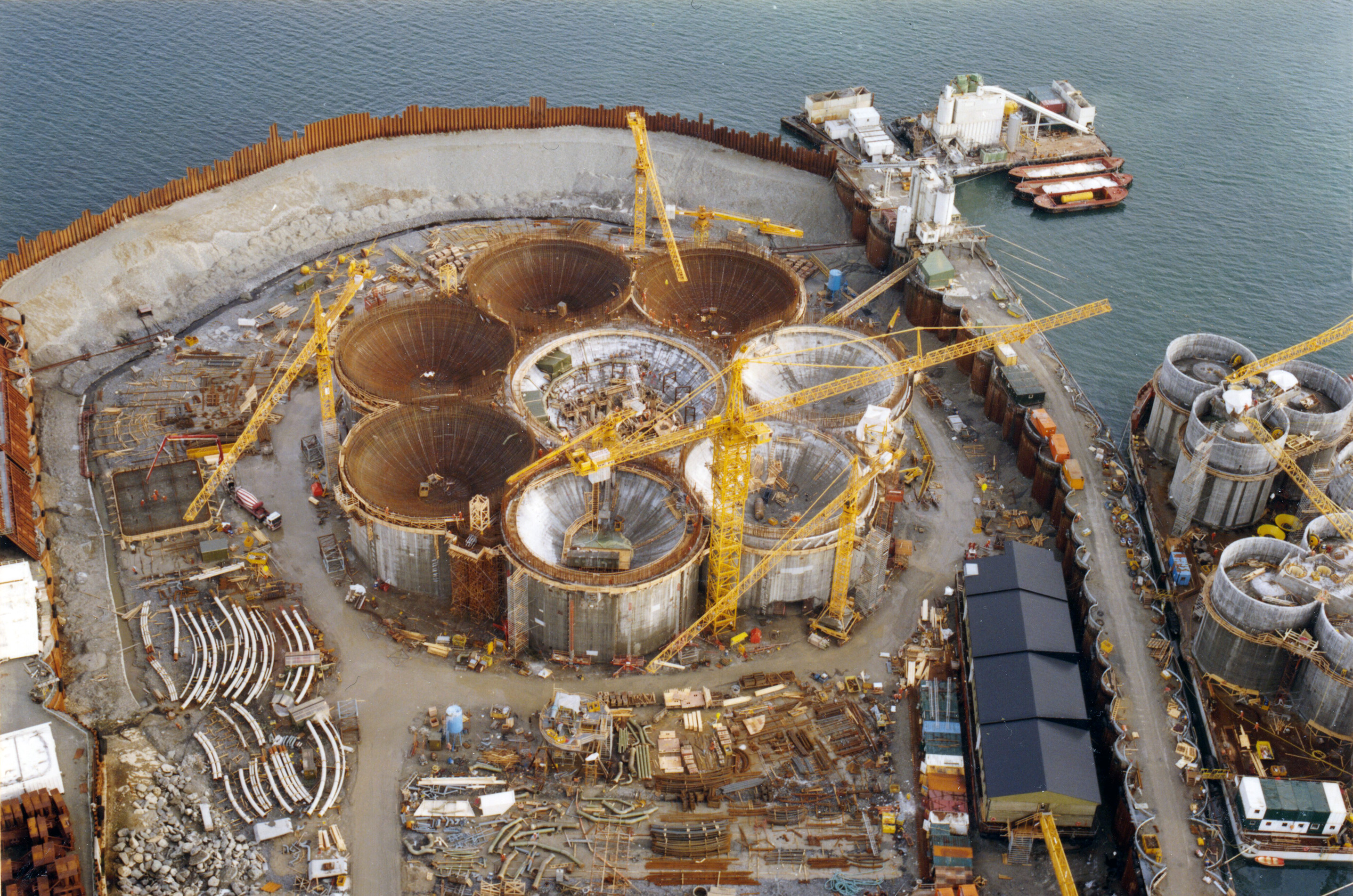
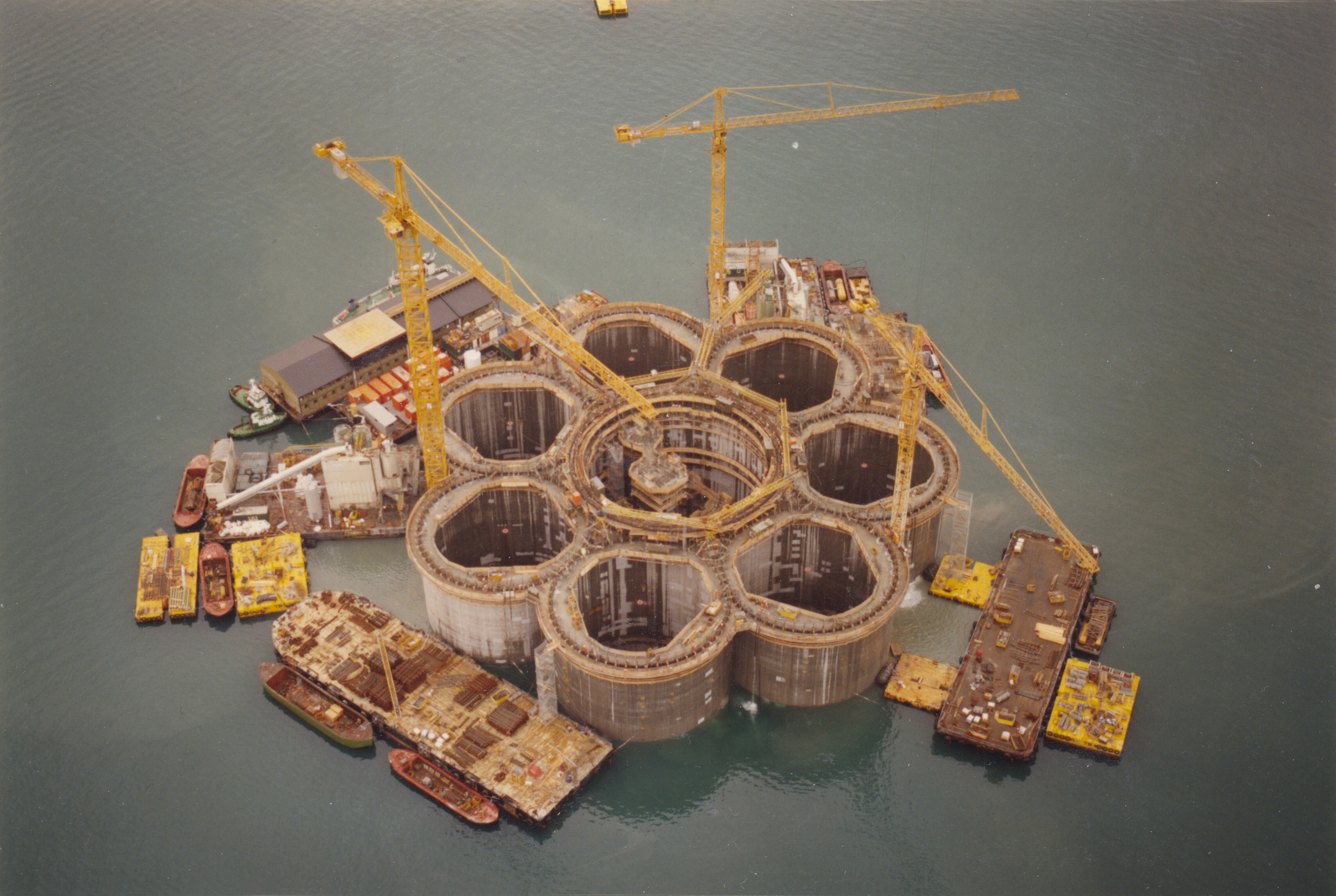
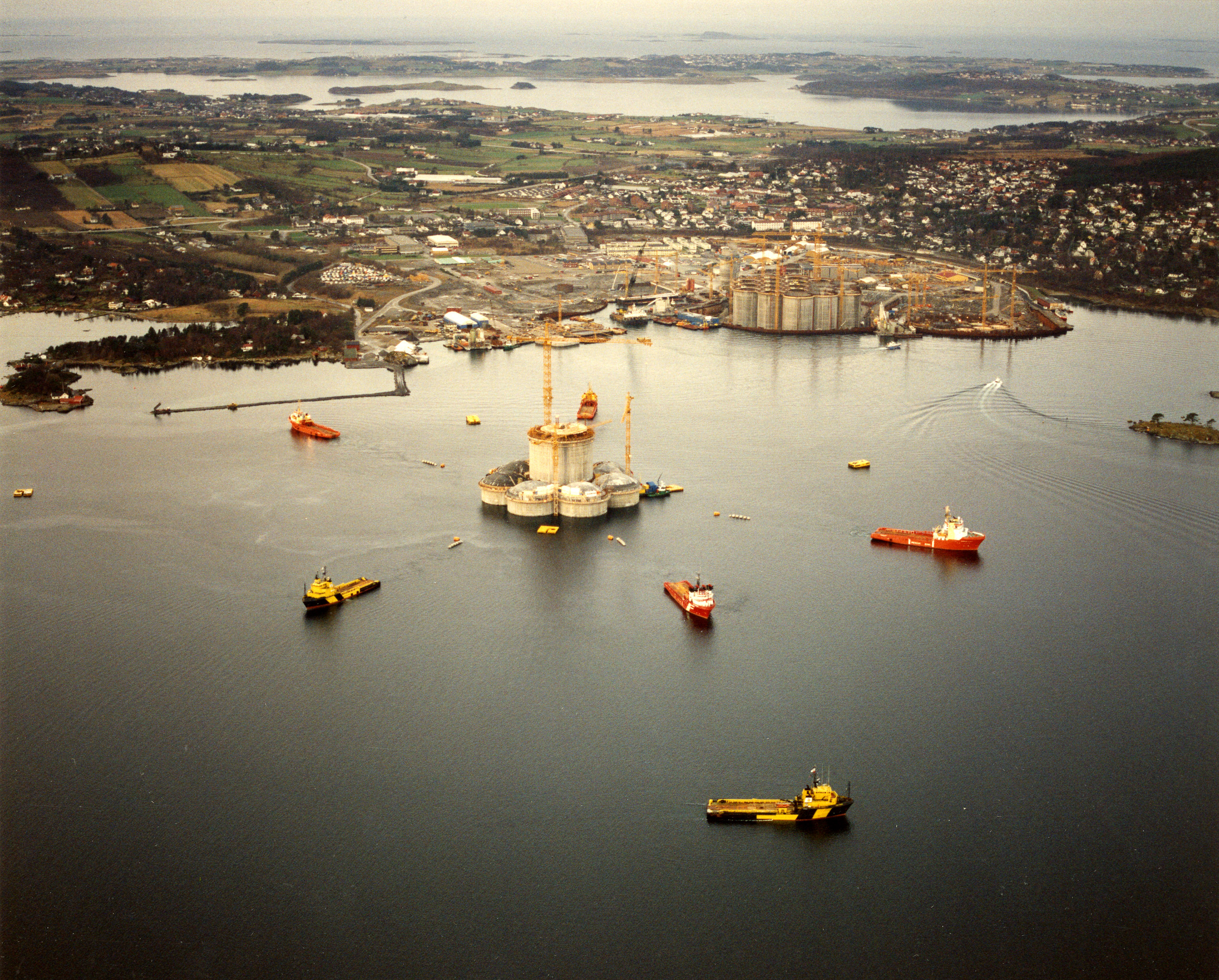
Three hectic months followed when the cell walls were cast to the desired height before the structure was floated out of the dry dock. The retaining wall was removed and air pumped into the space under the skirts to provide sufficient buoyancy.
Once the GBS was safely moored in the fjord during June 1991, work began to raise the support shaft to its planned height of 70 metres above the planned seabed level (ie, excluding the skirts).
At the same time, the storage cells were also readied for casting the domes which form their roofs. That work and further outfitting of the shaft took from August to December.
 bygging av betongdelen til plattformen, des 1991, engelsk
But further surprises were to hit the Draugen project. On the morning of 23 August 1991, the Sleipner A GBS vanished into the depths (see separate article).
Everyone involved in the various concrete GBS projects then under way got very concerned about what had happened and whether it would have any impact on their structure – including Draugen.
In an interview with local daily Stavanger Aftenblad, Shell project director Mahdi Hasan said that his company had full confidence in NC and saw no reason to be worried about progress.[REMOVE]Fotnote: Stavanger Aftenblad. (1991. 4. september). Shell har tillit til NC.
 Sleipner-havariet og Draugen, bygging, slep, engelsk,
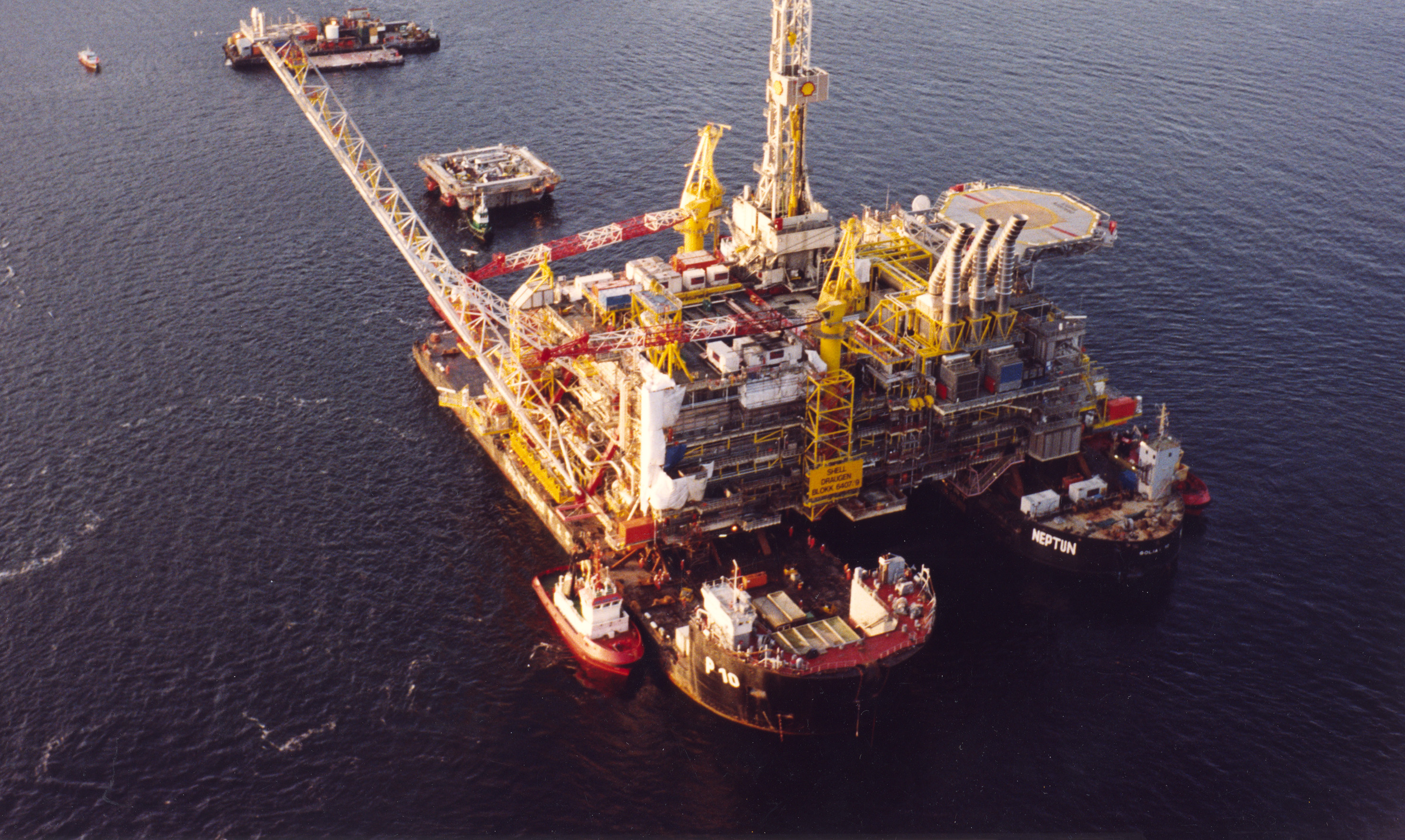
The Draugen GBS was readied for towing to Vats on the Yrkes Fjord further north, where the structure would be completed and mated with the topsides.
Because the shallow threshold at the mouth of the Gands Fjord imposes a significant draught restriction on towout, only the first two Condeeps – Beryl A and Brent B for the UK North Sea – were mated with their topsides there.
But the Draugen GBS’s special design and height also meant it could not be completed off Stavanger if it was to get across the threshold. Construction therefore had to be finalised at Vats.
Wolff recalls: “The most spectacular problem we had to overcome was discovered during trials with the GBS at a marine technology lab in Copenhagen during the summer of 1992.
“These were carried out to confirm the calculations already carried out. The 230-metre-high shaft has a conical form which widens out at the top to form a flat-sided cube.
“The model trials showed that the shaft would receive an extra blow when a high wave hit one of these flat sides, which transmitted extreme forces down the structure.
“These were up to 70 per cent in excess of those calculated and to some extent already built to. This violent response was dubbed ‘almost a new natural force’ among professionals. “The phenomenon was called ‘ringing’ because it was similar to the effect achieved when the clapper in an old-fashioned doorbell hits the gong.” (Read more in a separate article.)
Construction of the support shaft had already reached the halfway point, but was immediately halted in a bid to identify possible solutions.
This was a very dramatic position, which nobody involved had experienced before, and many began to doubt whether the platform could be usable at all.
An answer was nevertheless found fairly quickly. It comprised extending the shaft so much that the highest waves would not hit the flat sides.
The strength of the actual shaft also had to be boosted by utilising the extra reinforcement channels incorporated in the shaft in case some were filled with concrete during construction.
“We had just enough of these to be able to document satisfactory strength,” says Wolff. “A lot of people gave a sigh of relief at that.”
The GRP pipes mentioned above were also subject to an extra load which had not been taken into account when the GBS was designed.
Although the walls they passed through from the storage cells comprised heavily reinforced concrete more than two metres thick, they would be so deformed under maximum water pressure that the pipes could not cope.
By the time this was discovered, the structure had already been cast to a total height of 289 metres and towered almost 220 metres over the surface of the Yrkes Fjord.
To prevent big damage to the pipes from excessive deformation, this lower part of the platform was strengthened with more than 1 000 tonnes of reinforced concrete.
The latter was produced in a floating mixer station, lifted 220 metres to the top of the shaft by crane and then lowered roughly 280 metres to the internal basement of the GBS.
Wolff recalls a further incident when the concrete structure was moored at the point where the Vats Fjord meets the Yrkes Fjord, easily visible from the work camp on the western shore.
“Just after the basement had been reinforced, I received a call from Norske Shell’s project director, who was my opposite number under the contract.
“He shouted: ‘what’s happened to my platform, I can’t see it any more’. I looked out of my office window and couldn’t believe my eyes. The GBS was no longer there.
“Over by the eastern headland towards the Yrkes Fjord, however, the top of the shaft was visible. I got a sinking feeling – a mooring chain’s parted, I told myself.”
And that was exactly what had happed. One of the massive chains had broken, even though each link was more than a metre long, 60 centimetres wide and over 20 centimetres thick.
“We calculated later that if this had happened while mating with the topsides, when the GBS was ballasted down to a depth of more than 250 metres, it would have gone aground and suffered irreparable damage – another Condeep wreck.”
 bygging av betongdelen til plattformen, engelsk,
While awaiting the findings from the Copenhagen model trials and the changes made as a result, the mating was postponed from the original date in December 1992 to the following March.
But that caused no delays in completing the project. It simply left less time to check that everything was as it should be for hooking up pipework and control systems.
Everything appeared to be in order, but Wolff says that a senior subordinate entered his office the day after the successful mating with a particularly serious look on his face.
“He said: ‘I don’t think we can manage to install the platform on the field’. My first thought was that we’d had enough setbacks in one and the same project, but we’d overcome all the others …
“My colleague explained that a disastrous error had occurred when the GBS base was under construction in the dry dock at Jåttåvågen.
“The skirts are meant to penetrate eight-nine metres into the seabed, helping to stabilise the platform and transfer forces. They have thick walls which displace much of the seabed soil.
“That’s forced up and fills any cavities it finds – including in the three-sided spaces formed where any three of the cylindrical cells meet.
“Somebody had just checked how the structure had actually been cast in this area and discovered that these spaces were not hollow, but filled with concrete.
“This meant that the seabed material had nowhere to go when the skirts pressed down. That could cause a soil collapse, which would damage the whole GBS base and perhaps render it useless.”
NC had only a few weeks to find a solution which would satisfy everyone involved, says Wolff. “We poured over the map of the seabed, which gave very accurate depth information at a number of points on the platform site.
“The aim was to find slightly deeper places where the amount of soil to be displaced would be as small as possible. A programme was also produced to vary pressure under the platform so that the soil was drawn towards the areas under the main cells, where there was room for it, and away from the filled three-cornered spaces.”
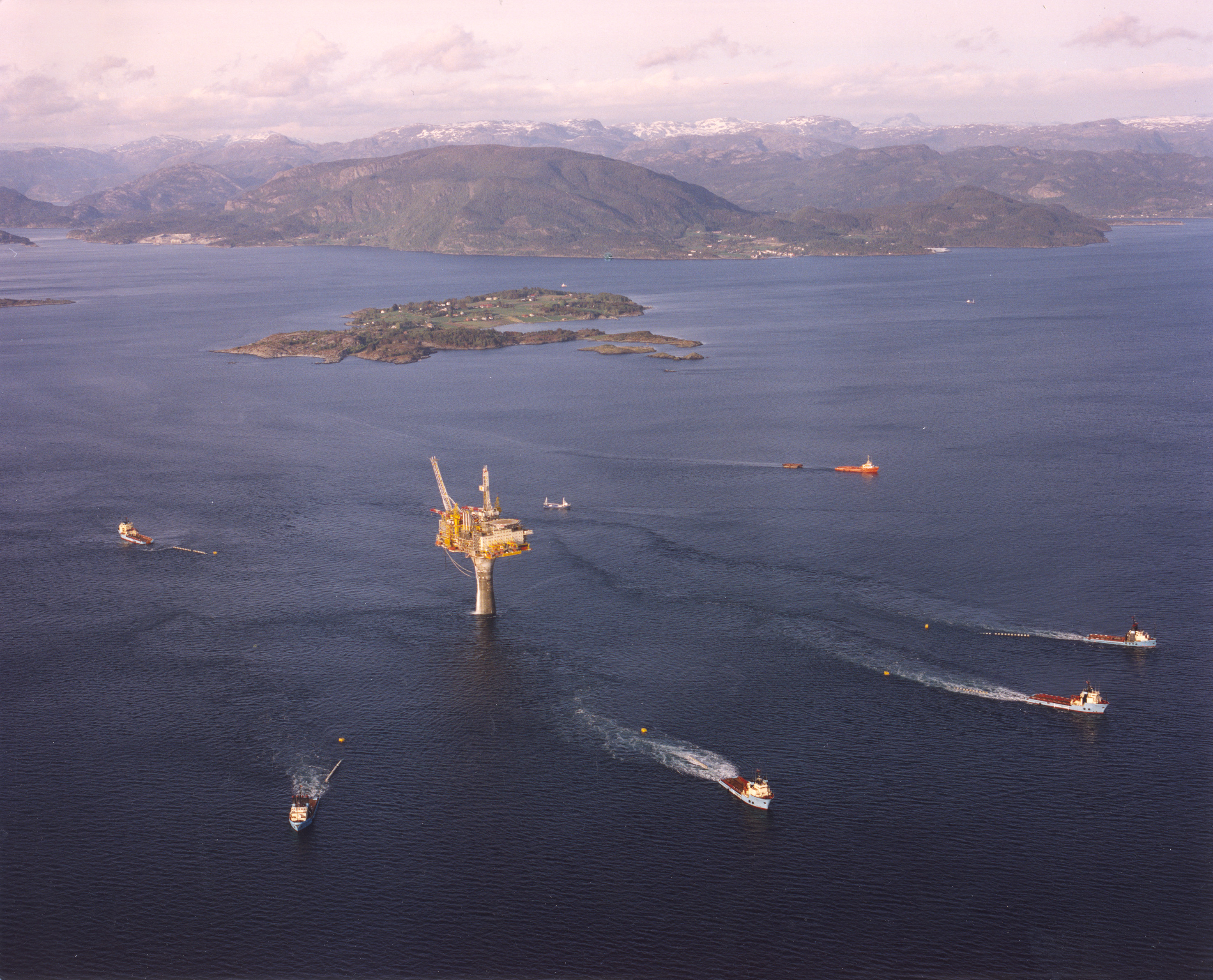
Read about the tow which began on 3 May 1993 and positioning the platform on the field on 16 May in a separate article.
 bygging av betongdelen til plattformen, utslep, engelsk,