
The topsides – design and content

 Dekket design og innhold, engelsk,
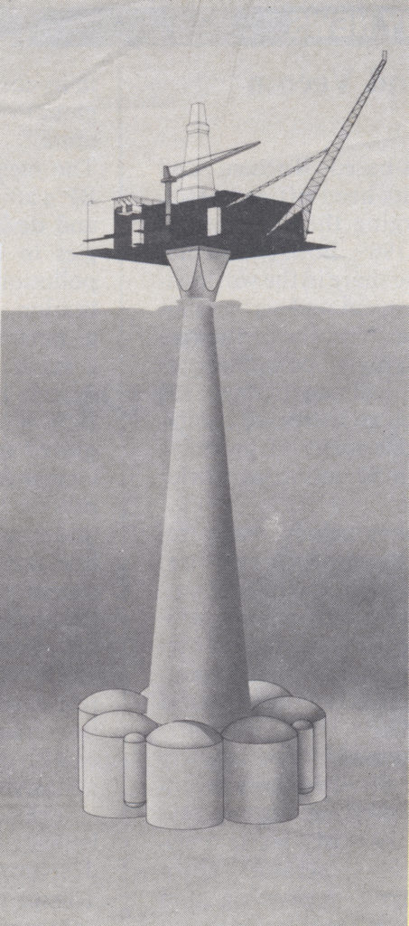
Operator Norske Shell’s main alternatives up to a final decision on the plan for development and operation (PDO) of Draugen were the concrete monotower or a floating unit.
Studies found that either a semi-submersible similar to a drilling rig or a tension-leg platform (TLP) would be the cheapest option.
But the final choice was determined by costs associated with operating and maintaining the support structure. A Condeep monotower made it possible to retain the basic topsides configuration without a new round of design and planning work.
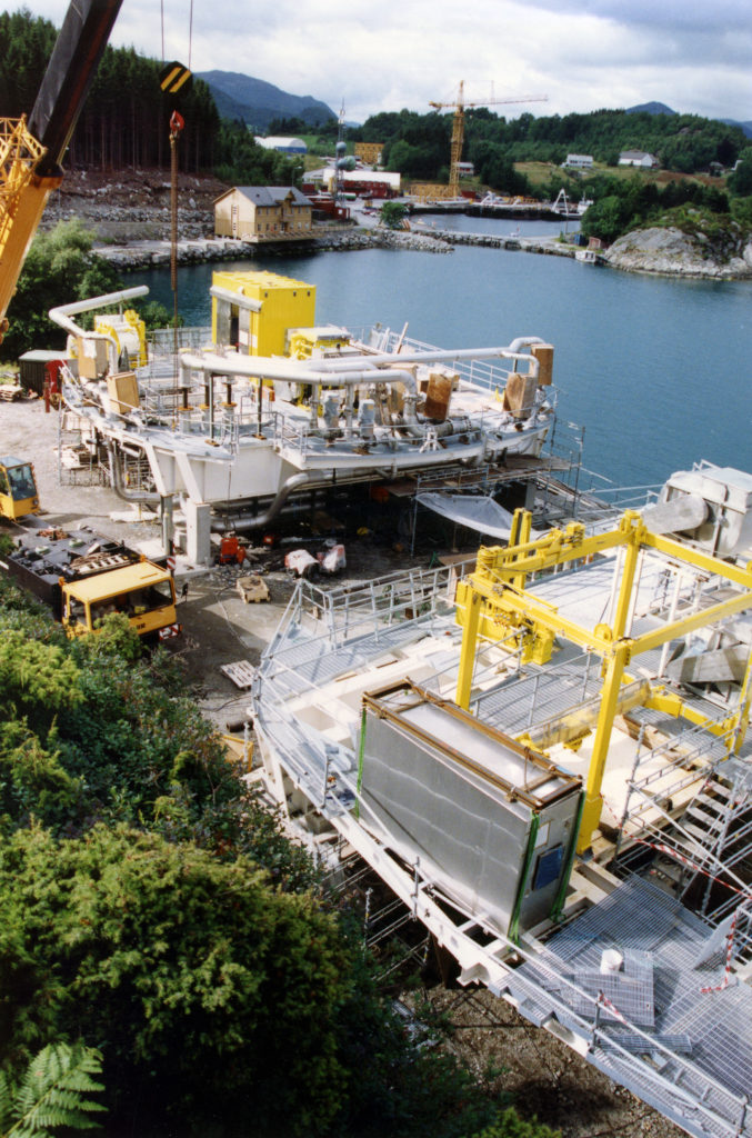
The integrated approach yielded a very compact topsides solution with an efficient relationship between weight and capacity.
With a footprint of 78 by 48 metres, including the external gangways, the topsides measure 32 metres in height from the top of the GBS shaft to the upper surface of the helideck.
The derrick adds almost 50 metres more, and the total height from the bottom edge of the GBS skirts to the derrick tip was about 370 metres.
Safety was a key factor from the very start in developing the platform concept, and the threat of explosion in its various areas came to have a big impact on the final solution.
In particular, the choice of an open truss construction and the use of floor gratings rather than deck plating reduced possible overpressures in the event of an explosion.[REMOVE]Fotnote: ockbain, G., Jermstad, A. (1990). Design of the Draugen Topsides for the Effects of Gas Explosions. Paper presentert på OTC 6477. Houston, Texas.
 Dekket design og innhold,
That also made an important contribution to keeping weight down. When the platform came on stream, the topsides had a dry weight of about 18 500 tonnes.
To optimise the topsides design, Kværner Engineering and Shell commissioned special calculations from the Christian Michelsen Institute in Bergen.
These utilised the flame acceleration simulator (Flacs) – a special computer programme developed at the research facility a few years earlier for several large international oil companies.[REMOVE]Fotnote: Gexcon. (2018). Flacs software. Hentet fra https://www.gexcon.com/products-services/FLACS-Software/22/en
Drilling
Achieving the output planned for the first year depended on being able to drill and produce oil in parallel through the single platform shaft. That was verified in a separate study.[REMOVE]Fotnote: SikteC A/S. (1991. august). Draugen GBS Shaft Safety Study – Management report. Report no. ST-91-CR-018-01.
The drilling equipment was integrated in the topsides, with the derrick movable so that it could be positioned over the relevant well slot. This structure was removed in 1997.
Work on preparing the rig for removal began on 10 April that year, and the last of 26 heavy lifts was completed on 10 May exactly a month later.[REMOVE]Fotnote: Shell UP. (1997). no 5, June: 14.
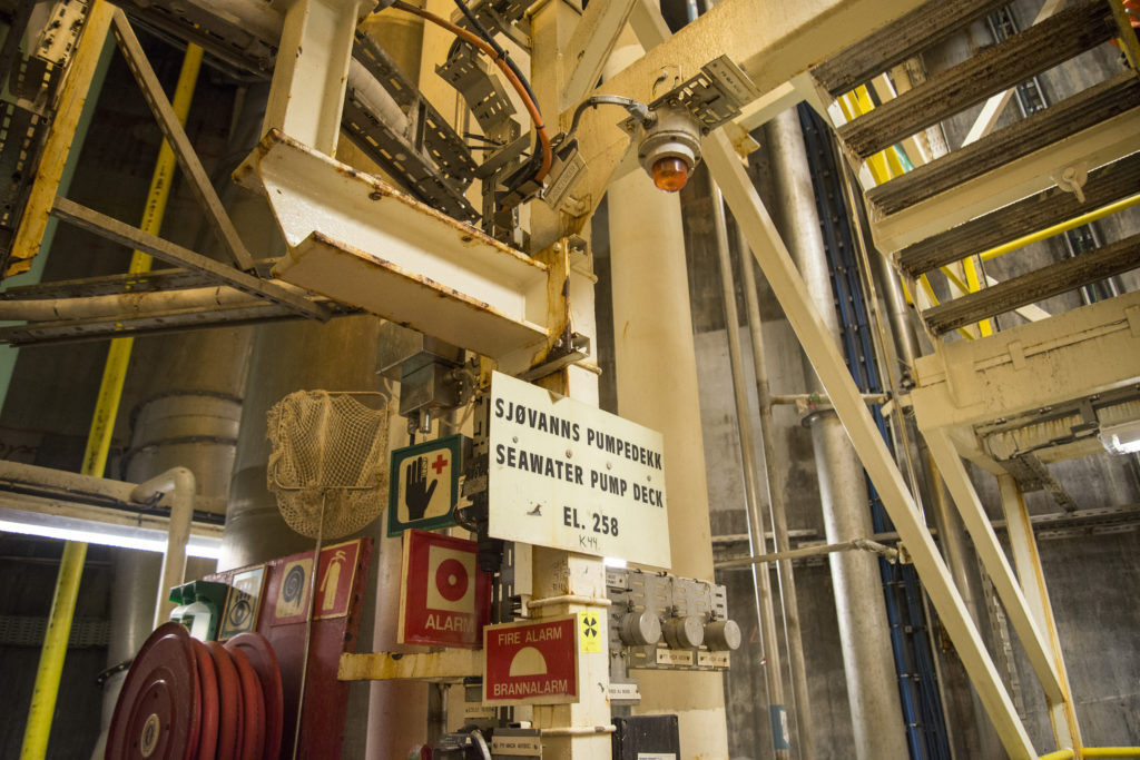
Water injection
Injecting water to maintain reservoir pressure was necessary from the start. This liquid has to be entirely free of harmful substances to avoid damaging the oil and gas resources.
Integrated with other seawater systems for cleaning and cooling, Draugen’s water injection system on includes filtration, deoxidisation, pumping, sterilising and chemical treatment.
Seawater enters the shaft at a depth of about 70 metres, where its quality is more than good enough for injection. Harmful seasonal plankton blooms occur much nearer the surface.
As an extra safeguard, a simple filtration system has nevertheless been installed at the platform intake. Chlorine is added to kill all possible organic material in the flow.
Oxygen is removed by passing the water through a vacuum chamber and, as a final precaution, chemicals are added to remove the last residues of undesirable components.
Main process equipment
 Dekket design og innhold, engelsk,
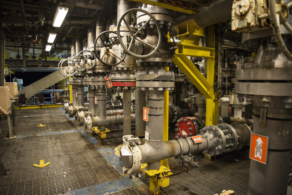
The main process equipment on the topsides is intended to meet the requirements set for producing, processing and exporting oil and gas. See the separate article for details of the process.
Utilities
This is a general term for all the systems required to operate the platform which are not directly involved in oil and gas production.
That includes direct process support as well as equipment for power generation and for living and working on a platform, such as safety, process control, heating and ventilation, and communication equipment.
Safety and security
Systems in this category are required for notifying and executing actions to prevent or reduce major or minor damage. They also include systems for emergency evacuation or for retrieving people who have fallen into the sea.
Alarms
These are intended to warn of incidents which require a coordinated commitment by all personnel to saving life and maintaining platform safety.
Alarms are given over the public address system, either as a signal or as a verbal announcement. Other alarms were located in areas which used to be protected by halon. A combination of sound and flashing lights, they gave personnel 10 seconds to leave.
Rescue/safety equipment
 Dekket design og innhold, overlevelsesdrakt, engelsk,
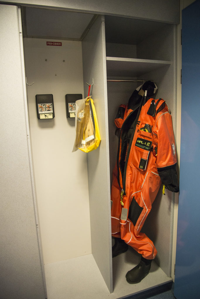
This is intended to permit speedy evacuation of personnel from the platform in an emergency, or to retrieve people who have fallen overboard.
It includes:
- covered free-fall lifeboats
- covered rafts which inflate on contact with the sea
- man-overboard boats (MOBs)
- chutes for evacuation to the sea
- personal survival suits.
Fire and gas detection
All areas of the platform are fitted with fire and gas detectors. Should fires or leaks be registered, the following actions are initiated automatically:
- fire pumps start
- sprinkler/deluge systems are initiated (halon has been phased out)
- fire dampers in the ventilation system are closed
- emergency shutdown (ESD) of the platform is initiated.
Fire extinguishing system
 Dekket design og innhold, engelsk,
This protects personnel, structures and equipment throughout the platform (including the shafts). Two types of system are installed:
- wet, using water or foam
- dry, using powder (and halon earlier).
The wet system is supplied by the fire water pumps installed on the service deck. Fixed foam extinguishers are positioned in areas with a high risk of oil fires.
Halon was originally used in technical spaces which contain much electrical and electronic equipment, but has been phased out. A large powder system has been installed in connection with the helideck.
In addition, fire extinguishers – both carbon dioxide and powder – have been positioned for quick response throughout the platform.
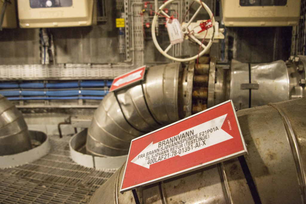
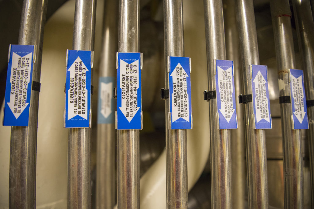
Water
 Dekket design og innhold,
The platform needs a lot of water for various purposes. Its sea and service water system is designed to supply all the liquid required for drilling, injection and ventilation systems, and to produce fresh water.
Separate systems are installed for fire and ballast water, while supplies for flushing are used to help wash sand out of the vessels used in the separation process.
Fresh water is produced from seawater with a maximum chlorine content of two parts per million (ppm). This is distilled in three evaporators.
Output from that process is cooled before being pumped via two units which regulate its acidity (pH) into storage tanks, which can also receive desalinated or potable (drinking) water pumped from supply ships.
Most of the fresh water is used for drinking, with some also consumed by cleaning and cooling. Potable water is supplied to the living quarters and selected areas elsewhere on the platform.
Desalinated water is pumped from one of the storage tanks via ultraviolet sterilisation units to consumer tanks located in the roof spaces of the living quarters.
Also called raw fresh water, desalinated service water is fresh water of secondary quality stored in a tank on the cellar deck and distributed by pumps for cleaning, drilling and refilling coolant water.
 Dekket design og innhold, engelsk,
Used in the coolers for gas and recovered oil, coolant water is a mix of three parts fresh water from the distribution system for desalinated water and one part monoethylene glycol from the glycol system, giving a freezing point of -12°C. A small amount of corrosion inhibitor is added.
Hot water is produced to provide a reliable heat source with a constant temperature for the following applications:
- desalination of seawater in the evaporators
- heating and ventilation systems (except in the living quarters, which have electrical heaters)
- supplies of coolant water to the circulation pump for hot medium.
Steam is produced in a generator with a pressure of eight bar for cleaning process vessels and for various other types of cleaning. The steam generator is a heat exchanger.
Heating, ventilation and air conditioning
These functions are split into two separate systems, covering the production area and the living quarters respectively.
The system for the production area is designed to deliver air at a specified temperature and pressure to the platform’s areas. This is intended in turn to reduce risk and accidents in spaces where fire and explosion are hazards (see compressed air below).
Provision of such air is crucial for safe operation of the platform. Should the system fail for any reason, the process plant must be shut down immediately.
Heating and ventilation of the living quarters involve a completely separate system, which functions in the same way as an installation in a normal building on land.
The heating medium system
serves as a heat source for:
- the circulating hot water system for desalination of seawater and space heating, with the exception of the electrically heated living quarters
- steam generation
- superheating of sludge
- sludge treatment
- stabilising condensate
- glycol distillation.
The heat source is a refined paraffin circulated to the user sites, where it is heated in furnaces over an open flame and in three recovery units for waste heat.
Air conditioning in the living quarters serves cabins, recreation areas and the galley. Located in the ventilation room on the service floor, it sucks in fresh air and delivers it at a predetermined pressure, temperature and humidity to the whole living quarters.
A helideck heating system keeps the deck free of ice, maintains the temperature of the fuel gas and the process gas piping to prevent formation of condensate and hydrate (hydrocarbon ice) respectively, and prevents the fire and injection water systems from freezing.
Heating cables are located in channels under the helideck, with electrical heating strips installed externally on piping. These activate automatically if the ambient temperature drops below 5°C.
Compressed air
In a process facility where explosive gases could build up, electrical instruments and spaces containing such equipment must be kept at a pressure above the surrounding plant.
This is intended to prevent gas from entering and being ignited by electrical sparks. A dedicated system provides a reliable source of clean compressed air for instrument and working atmospheres.
Sewage treatment
This system collects all sewage and waste water for treatment and subsequent discharge to the sea. Most of the sewage comes from toilets, showers, washbasins, kitchen sinks and washing machines in the living quarters.
It is conducted by gravity and negative pressure to septic tanks. A filter removes solid particles, which are then sent to mills for grinding to a liquid sludge.
All bacteria in the sewage – particularly coliforms – are killed by chlorine injection before treated waste is discharged to the sea 10 metres below its surface. If necessary, raw sewage can be discharged to a barge through a hose connection for disposal on land.
Fuel
Two types of fuel are needed on the platforms – helicopter (aviation) fuel and diesel oil for power generation and other specialised machinery.
Supplies are brought in by ships equipped with special tanks for helicopter fuel. These can also pump diesel oil directly via hoses to special storage tanks in one of GBS cells.
Lubricating oil
This system distributes various types of lube oil to the main systems through a permanent piping network.
From the filling (tote) tanks, they are piped via lube oil distribution tanks to the most important consumers – gas turbines, generators, water injection pumps and fire pumps.
Other types of oils/lube oils are also required on board, but the level of consumption does not warrant a fixed distribution system for them.
Chemicals
A great many different chemicals and chemical compounds are used on the Draugen platform for such purposes as separating oil and water.
Other applications include inhibiting or breaking down oil droplets in the produced water (emulsions), which is separated from the crude oil flow.
Chemicals also prevent or stabilise foaming, or inhibit hydrate (hydrocarbon ice) formation, bacterial growth or corrosion.
These substances are shipped out to the platforms on supply vessels. Among the commonest are the following.
- Methanol is used to prevent the formation of hydrate plugs in pipelines, which can halt liquid flow. When gas contains small quantities of water, ice-like clumps can form under special pressure and temperature conditions.
- Glycol primarily serves an agent for removing water from rich gas because it acts as an efficient absorber of water. It is also used in coolant systems to reduce the freezing point to -12°C.
- Chlorine can be added to seawater to prevent the growth of bacteria in pipelines and ballast water, seawater and fire water systems. Sodium hydrochlorite (NaOCI) or bleach is used to kill unwanted organisms.
- Corrosion inhibitor is added to prevent internal corrosion in piping and tanks. The substances used are usually based on organic compounds which form a protective film on metals.
- Bactericides are deployed to control the growth of bacteria in water and hydrocarbons. The most serious problem for oil and gas production is provided by sulphate-reducing bacteria which develop hydrogen sulphide (H2S). This substance is not only toxic but also both explosive and extremely corrosive.
- Anti-foaming agents are used to prevent foaming in the main process, and are injected ahead of the separator tanks in order to ensure that separation of water, oil and gas is as efficient as possible.
Transfer and metering systems
Crude oil is transferred from the storage cells to loading buoy via a discharging system which includes powerful pumps installed on top of the shaft.
The transfer then passes via smaller export pumps and the fiscal metering system, which measures the quantity being exported before entering a dedicated flowline system.
Accurate fiscal metering is important, since the licensees must feel confident that the quantities registered are correct and the tax authorities also have to be convinced. A special system therefore conducts regular checks.
Power supply
Electricity required to operate the platform can be generated by three gas turbines which each have the capacity to meet 50 per cent of maximum power requirements on board.
This means that, if one turbine is temporarily out of operation because of repairs and maintenance, sufficient capacity remains to keep the platform running.
Mains electricity is supplied by three 19-megawatt generators as a 13.8 kilovolt, three-phase 60 Hertz current. The generators are driven by gas/diesel turbines.
Emergency power is supplied by three 1.18 MW generators which start up automatically and connect to a 6 kV panel. If both main and emergency power systems fail, supplies of alternating and direct current will be maintained by batteries.
Electricity for the living quarters comprises the normal supply of alternating current, and emergency supplies of both alternating and direct current.
The normal supply is used for air conditioning, galley equipment, heating, hot water, laundry, lifts, lighting, refrigerators, waste units and ventilation.
Emergency supplies are used to maintain necessary lighting and electronic equipment.
Monitoring and control
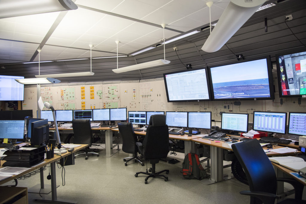 Dekket design og innhold,
The monitoring and control systems on Draugen are located in a central control room (CCR), and ensure an efficient, safe and reliable automated process. Placing the whole monitoring system in the CCR reduces personnel exposure to the production area.
Process control monitors and controls all systems on the platform to ensure that hydrocarbons can be produced as safely as possible. The main functions involve maintaining a check on:
- data transmission between the production system and the control-room terminals
- analogue operating commands
- automatic switches and logical sequence control commands
- alarm logging.
All this information is monitored from the CCR. Printers and displays for alarms and trends are also concentrated there to provide the operators with a good and accurate picture of conditions at all times.
Safety monitoring is a system intended to handle “all” aspects of safety on the platform. Field instrumentation and sensors for fire and gas alarms monitor the whole process and every area.
The purpose of the system is to initiate production ESD when the process monitoring system fails to handle the problems which might occur.
In principle, it comprises two sub-systems.
- Process shutdown monitors the process and shuts it down if control is lost, and thereby prevents the plant being operated in a hazardous manner – under pressures higher than the tanks are designed to handle, for example.
- ESD is initiated if hazardous conditions arise – such as a gas leak or a fire. This system receives signals from fire and gas detectors as well as from manual alarms.
The metering system for production and consumption meters the quantity of gas and oil exported from the platform as well as the amount of consumption and fuel gas used internally.
This system attracts great attention from all levels of the organisation, since its measurements form the basis for the revenues generated and the tax to be paid on output.
Systems for telecommunications and pollution control have been constantly replaced and improved in line with technological advances and changing regulatory requirements.
Loading/discharging
The loading/discharging system is designed to handle supplies brought in or taken away by sea.
Cranes
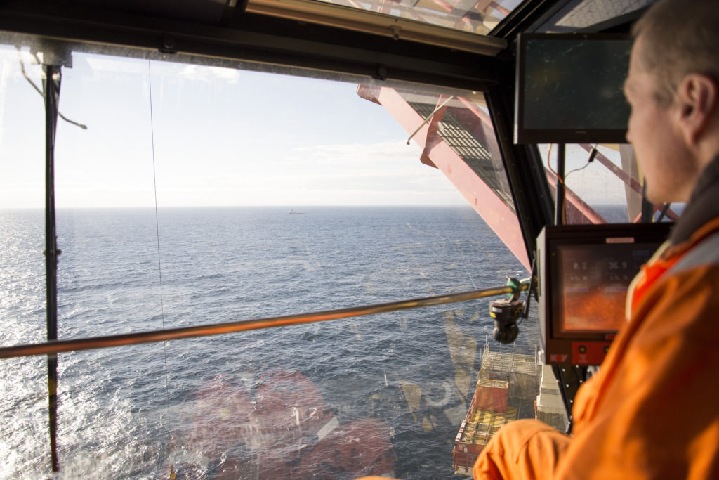 Dekket design og innhold, engelsk,
Cranes on the platform are used for:
- lifting from or discharging to supply ships
- maintenance and construction lifting over the whole platform and in the equipment shaft
- handling pipes and equipment.
Bulk handling
Equipment for bulk handling is used to transport, handle and store various liquids, powders, gases and chemicals required for the platform’s process system and utilities. These products are brought out by supply ships and transferred to the platform either in tanks or via hoses.
Tanks and other bulk containers are lifted by crane from the supply ship to the platform’s storage area on the open deck. Liquids used in large volumes are transferred via permanently installed piping to the fixed storage tanks. Empty tanks are discharged for return to land.
Diesel oil, fresh water, barytes, gel and cement are transferred to the platform’s bulk storage tanks with the aid of hoses lowered to the supply ship.
Living quarters
This part of the platform provides accommodation, recreation and catering for all operational phases. About 60 people will be on board during normal operation, but full service can be provided for 150.
To give the best protection against possible incidents in the well area, the quarters are insulated from the rest of the topsides by a high-performance fire and explosion wall.
This covers the full width and height of the quarters, while a similar wall separates the production section from the area where the wellstream reaches the topsides.
Read more in a separate article on the role of the architect.