
Squaring the circle

A technique known as “gliding formwork” or “slipforming” was used to construct the vertical sections of the concrete gravity base structures (GBSs) built in Stavanger and elsewhere. This was a special form of a “climbing formwork”, where a form is constructed and then disassembled once casting has been completed. It can then be reinstalled to cast the next section. That approach is preferred when constructing vertical sections of limited height, such as in residential properties or foundations.
Such cases involve a limited number of disassembly/reassembly operations. The method is advantageous where many cutouts – such as windows – are involved. Slipforming was the best approach for the big concrete GBSs because it permitted continuous construction with few joints and cost-efficient working.
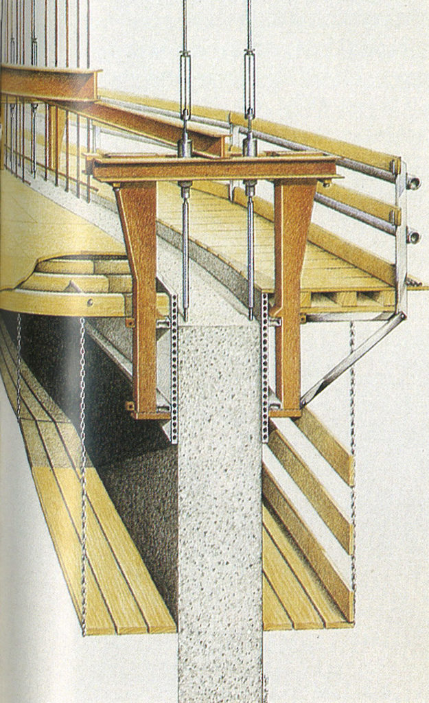
Figure 2 shows how this is typically built up. The actual formwork comprises a vertical sheet installed to ensure that wall thickness and shape meet the design specifications.
Gangways are installed on both sides of the wall around the whole circumference to provide a work space and access for such jobs as installing reinforcement bars (rebars) and cutouts. Other tasks here include pouring concrete into the forms, applying epoxy, inspecting the finished result and repairing possible surface blemishes.
Formwork and gangways are attached to frames hung from hydraulic jacks, which move up as the structure rises. If the design requires changes in diameter, the formwork radius can be adjusted with a horizontal jacking system.
 sirkelens kvadratur, engelsk
As concrete is cast, the whole formwork get raised by activating the jacks simultaneously. Adjusted to the curing time of the concrete, the speed of the glide will vary with complexity and volume and is normally 1.5 to four metres per day.
The jacks are constantly adjusted to adapt the formwork to the desired shape of the concrete wall and to correct possible variations without exceeding tolerances specified in the chosen building standard.
Careful control of shaft geometry is exercised with the aid of laser measurements to ensure that all dimensions meet the tolerances throughout.
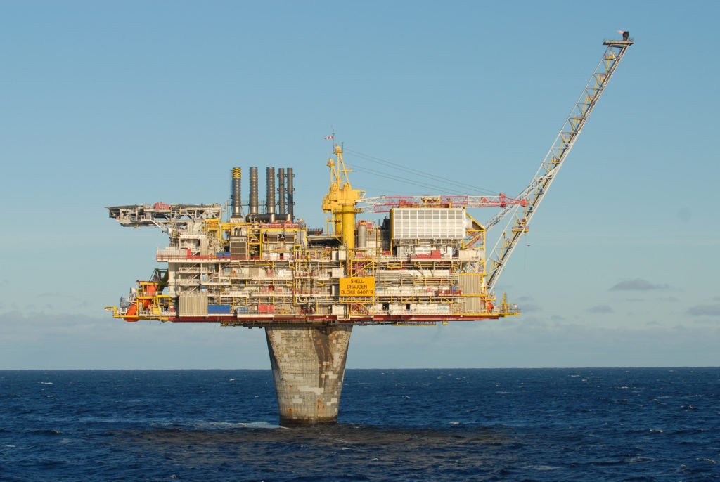
The conical shaft in the Draugen GBS has its narrowest diameter at the sea surface, where it measures just over 15 metres compared with more than 22 metres down at the storage cells.
That reduces wave forces acting on the platform and thereby allows its base section to be reduced, as well as securing a more efficient design.
However, a circular cross-section with a relatively small diameter was not the optimal solution for the transition to the square topside.
The top of the shaft was accordingly designed as a box structure with a square cross-section measuring 22 metres to a side.
Designing and operating a slipforming process where the cross-section gradually changed from circle to square therefore presented a challenge in construction terms.
This required both a variation in wall thickness and an increase in external dimensions – squaring the circle in practice.[REMOVE]Fotnote: Tegning GS D 2001-001 GENERAL VIEW
The solution involved a system which made it possible to add additional formwork sheets as the slipformed area increased, and creating a frame with arms which stuck out from the centre.
A horizontal jacking system controlled the distance from the centre to the formwork, and this approach provided a successful outcome.
The formwork could be raised so that the shaft wall became a double arc with its external dimensions tailored to a favourable solution for designing and attaching the topsides.
One result of this building technique was that a checked pattern emerged on the transition piece, which gives the Draugen platform a characteristic appearance.
 sirkelens kvadratur, engelsk,
Based on an e-mail from Dag N Jensen, former head of engineering design at Norwegian Contractors.